
ϑ 4/3 and 4/2 directional valve ϑ with hand lever actuation · 4/3 and 4/2 directional valve with...
12
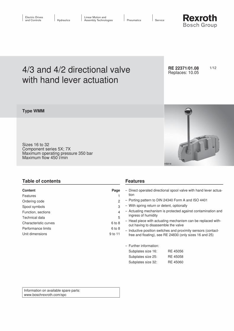
1/12 Information on available spare parts: www.boschrexroth.com/spc 4/3 and 4/2 directional valve with hand lever actuation Type WMM Sizes 16 to 32 Component series 5X; 7X Maximum operating pressure 350 bar Maximum flow 450 l/min RE 22371/01.08 Replaces: 10.05 Table of contents Features – Direct operated directional spool valve with hand lever actua- tion – Porting pattern to DIN 24340 Form A and ISO 4401 – With spring return or detent, optionally – Actuating mechanism is protected against contamination and ingress of humidity – Head piece with actuating mechanism can be replaced with- out having to disassemble the valve – Inductive position switches and proximity sensors (contact- free and floating), see RE 24830 (only sizes 16 and 25) – Further information: Subplates size 16: RE 45056 Subplates size 25: RE 45058 Subplates size 32: RE 45060 H5914 Content Page Features 1 Ordering code 2 Spool symbols 3 Function, sections 4 Technical data 5 Characteristic curves 6 to 8 Performance limits 6 to 8 Unit dimensions 9 to 11
Transcript of ϑ 4/3 and 4/2 directional valve ϑ with hand lever actuation · 4/3 and 4/2 directional valve with...
1/12
Information on available spare parts: www.boschrexroth.com/spc
4/3 and 4/2 directional valve with hand lever actuation
Type WMM
Sizes 16 to 32Component series 5X; 7XMaximum operating pressure 350 barMaximum flow 450 l/min
RE 22371/01.08Replaces: 10.05
Table of contents Features
– Direct operated directional spool valve with hand lever actua-tion
– Porting pattern to DIN 24340 Form A and ISO 4401– With spring return or detent, optionally– Actuating mechanism is protected against contamination and
ingress of humidity– Head piece with actuating mechanism can be replaced with-
out having to disassemble the valve– Inductive position switches and proximity sensors (contact-
free and floating), see RE 24830 (only sizes 16 and 25)
– Further information: Subplates size 16: RE 45056 Subplates size 25: RE 45058 Subplates size 32: RE 45060
H5914
Content PageFeatures 1Ordering code 2Spool symbols 3Function, sections 4Technical data 5Characteristic curves 6 to 8Performance limits 6 to 8Unit dimensions 9 to 11
InhaltTable of contents 1Features 1Ordering code 2Spool symbols 3Function, sections 4Technical data (for applications outside these parameters, please consult us!) 5Characteristic curves: Size 16 (measured with HLP46, ϑoil = 40 °C ±5 °C) 6Performance limits: Size 16 (measured with HLP46, ϑoil = 40 °C ±5 °C) 6Characteristic curves: Size 25 (measured with HLP46, ϑoil = 40 °C ±5 °C) 7Performance limits: Size 25 (measured with HLP46, ϑoil = 40 °C ±5 °C) 7Characteristic curves: Size 32 (measured with HLP46, ϑoil = 40 °C ±5 °C) 8Performance limits: Size 32 (measured with HLP46, ϑoil = 40 °C ±5 °C) 8Unit dimensions: Size 16 (dimensions in mm) 9Unit dimensions: Size 25 (dimensions in mm) 10Unit dimensions: Size 32 (dimensions in mm) 11Notes 12
2/12 Bosch Rexroth AG Hydraulics WMM RE 22371/01.08
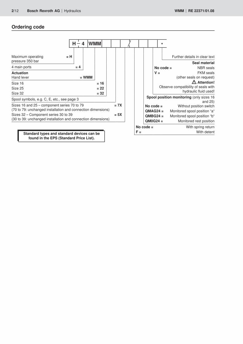
Maximum operating = H pressure 350 bar
4 main ports = 4Actuation Hand lever = WMMSize 16 = 16Size 25 = 22Size 32 = 32Spool symbols, e.g. C, E, etc., see page 3Sizes 16 and 25 – component series 70 to 79 = 7X (70 to 79: unchanged installation and connection dimensions)Sizes 32 – Component series 30 to 39 = 5X (30 to 39: unchanged installation and connection dimensions)
Further details in clear textSeal material
No code = NBR seals V = FKM seals
(other seals on request) Attention!
Observe compatibility of seals with hydraulic fluid used!
Spool position monitoring (only sizes 16 and 25)
No code = Without position switchQMAG24 = Monitored spool position “a“QMBG24 = Monitored spool position “b“QM0G24 = Monitored rest position
No code = With spring returnF = With detent
H 4 WMM *
Ordering code
Standard types and standard devices can be found in the EPS (Standard Price List).
A B
P T
a b
A B
P T
a b
a b
A B
P T
a b
A B
P T
a b
a b
= C
= D
= K
= Z
= L
= M
= E
= F
= G
= H
= J
A B
P T
a 0 a 0
A B
P T
b ba b
= R
= T
= U
= V
= W
= P
= Q
A B
P T
a 0 a 0
A B
P T
b ba b
= S 1)
Hydraulics Bosch Rexroth AGRE 22371/01.08 WMM 3/12
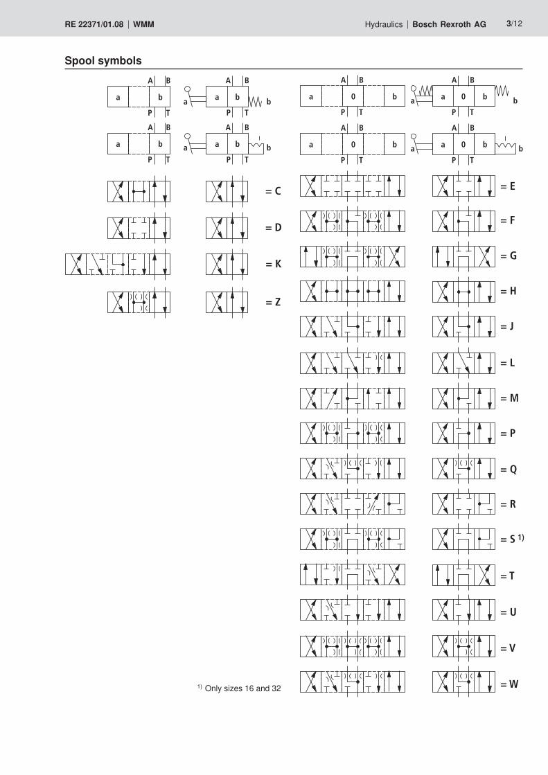
Spool symbols
1) Only sizes 16 and 32
AL P B T
1
2
3 4
5
2
5 6
4/12 Bosch Rexroth AG Hydraulics WMM RE 22371/01.08
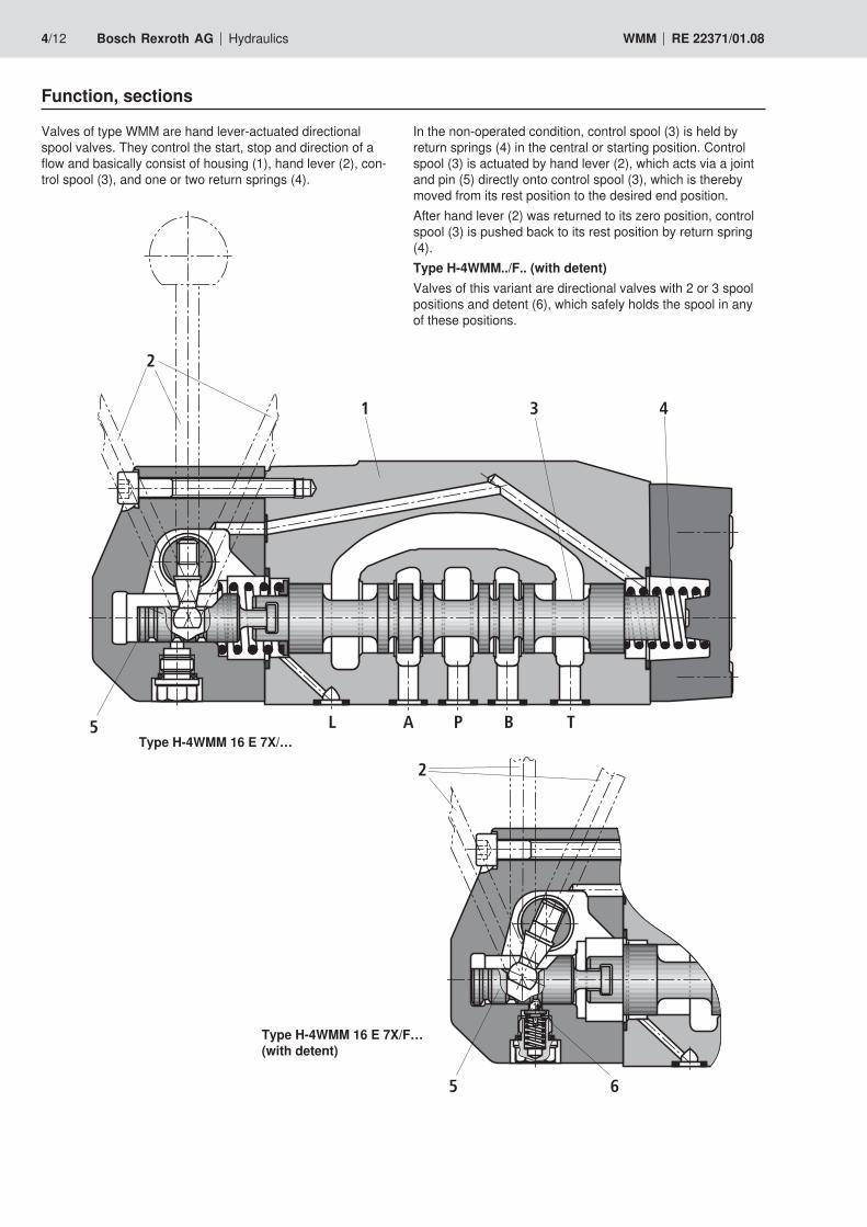
Function, sections
Valves of type WMM are hand lever-actuated directional spool valves. They control the start, stop and direction of a flow and basically consist of housing (1), hand lever (2), con-trol spool (3), and one or two return springs (4).
In the non-operated condition, control spool (3) is held by return springs (4) in the central or starting position. Control spool (3) is actuated by hand lever (2), which acts via a joint and pin (5) directly onto control spool (3), which is thereby moved from its rest position to the desired end position.After hand lever (2) was returned to its zero position, control spool (3) is pushed back to its rest position by return spring (4). Type H-4WMM../F.. (with detent)Valves of this variant are directional valves with 2 or 3 spool positions and detent (6), which safely holds the spool in any of these positions.
Type H-4WMM 16 E 7X/…
Type H-4WMM 16 E 7X/F… (with detent)
Hydraulics Bosch Rexroth AGRE 22371/01.08 WMM 5/12
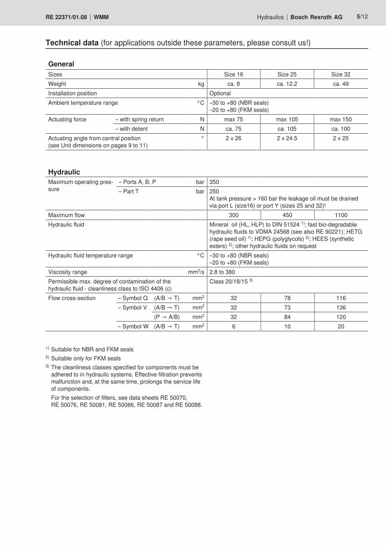
Technical data (for applications outside these parameters, please consult us!)
GeneralSizes Size 16 Size 25 Size 32 Weight kg ca. 8 ca. 12.2 ca. 49Installation position OptionalAmbient temperature range °C –30 to +80 (NBR seals)
–20 to +80 (FKM seals)Actuating force – with spring return N max 75 max 105 max 150
– with detent N ca. 75 ca. 105 ca. 100Actuating angle from central position (see Unit dimensions on pages 9 to 11)
° 2 x 26 2 x 24.5 2 x 25
HydraulicMaximum operating pres-sure
– Ports A, B, P bar 350– Part T bar 250
At tank pressure > 160 bar the leakage oil must be drained via port L (size16) or port Y (sizes 25 and 32)!
Maximum flow 300 450 1100Hydraulic fluid Mineral oil (HL, HLP) to DIN 51524 1); fast bio-degradable
hydraulic fluids to VDMA 24568 (see also RE 90221); HETG (rape seed oil) 1); HEPG (polyglycols) 2); HEES (synthetic esters) 2); other hydraulic fluids on request
Hydraulic fluid temperature range °C –30 to +80 (NBR seals)–20 to +80 (FKM seals)
Viscosity range mm2/s 2.8 to 380Permissible max. degree of contamination of the hydraulic fluid - cleanliness class to ISO 4406 (c)
Class 20/18/15 3)
Flow cross-section – Symbol Q (A/B → T) mm2 32 78 116– Symbol V (A/B → T) mm2 32 73 136
(P → A/B) mm2 32 84 120– Symbol W (A/B → T) mm2 6 10 20
1) Suitable for NBR and FKM seals2) Suitable only for FKM seals3) The cleanliness classes specified for components must be
adhered to in hydraulic systems. Effective filtration prevents malfunction and, at the same time, prolongs the service life of components.
For the selection of filters, see data sheets RE 50070, RE 50076, RE 50081, RE 50086, RE 50087 and RE 50088.
14
12
10
8
6
4
2
0 100 200 300
1
5
2
4
3
768
6/12 Bosch Rexroth AG Hydraulics WMM RE 22371/01.08
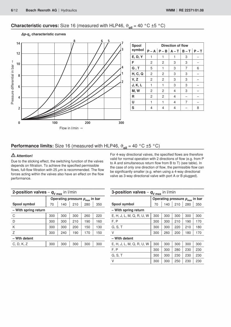
Characteristic curves: Size 16 (measured with HLP46, ϑoil = 40 °C ±5 °C)
Flow in l/min →
Pres
sure
diff
eren
tial in
bar
→
∆p-qV characteristic curves
Performance limits: Size 16 (measured with HLP46, ϑoil = 40 °C ±5 °C)
Attention!Due to the sticking effect, the switching function of the valves depends on filtration. To achieve the specified permissible flows, full-flow filtration with 25 µm is recommended. The flow forces acting within the valves also have an effect on the flow performance.
2-position valves – qV max in l/min
Spool symbolOperating pressure pmax in bar70 140 210 280 350
– With spring returnC 300 300 300 260 220D 300 300 210 190 160K 300 300 200 150 130Z 300 240 190 170 150– Wth detentC, D, K, Z 300 300 300 300 300
Spool symbol
Direction of flowP – A P – B A – T B – T P – T
E, D, Y 1 1 1 3 –F 2 2 3 3 –G , T 5 1 3 7 6H, C, Q 2 2 3 3 –V, Z 2 2 3 3 –J, K, L 1 1 3 3 –M, W 2 2 4 3 –R 2 2 4 – –U 1 1 4 7 –S 4 4 4 – 8
For 4-way directional valves, the specified flows are therefore valid for normal operation with 2 directions of flow (e.g. from P to A and simultaneous return flow from B to T) (see table). In the case of only one direction of flow, the permissible flow can be significantly smaller (e.g. when using a 4-way directional valve as 3-way directional valve with port A or B plugged).
3-position valves – qV max in l/min
Spool symbolOperating pressure pmax in bar70 140 210 280 350
– With spring returnE, H, J, L, M, Q, R, U, W 300 300 300 300 300F, P 300 300 210 190 170G, S, T 300 300 220 210 180V 300 260 200 180 170– With detentE, H, J, L, M, Q, R, U, W 300 300 300 300 300F, P 300 300 280 230 230G, S, T 300 300 230 230 230V 300 300 250 230 230
14
12
10
8
6
4
2
0 100 200 300 400 450
1
23
465
Hydraulics Bosch Rexroth AGRE 22371/01.08 WMM 7/12
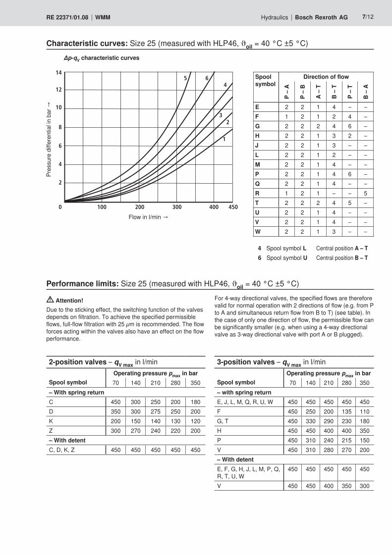
Characteristic curves: Size 25 (measured with HLP46, ϑoil = 40 °C ±5 °C)
Flow in l/min →
Pres
sure
diff
eren
tial in
bar
→∆p-qV characteristic curves
Performance limits: Size 25 (measured with HLP46, ϑoil = 40 °C ±5 °C)
Attention!Due to the sticking effect, the switching function of the valves depends on filtration. To achieve the specified permissible flows, full-flow filtration with 25 µm is recommended. The flow forces acting within the valves also have an effect on the flow performance.
2-position valves – qV max in l/min
Spool symbolOperating pressure pmax in bar70 140 210 280 350
– With spring returnC 450 300 250 200 180D 350 300 275 250 200K 200 150 140 130 120Z 300 270 240 220 200– With detentC, D, K, Z 450 450 450 450 450
For 4-way directional valves, the specified flows are therefore valid for normal operation with 2 directions of flow (e.g. from P to A and simultaneous return flow from B to T) (see table). In the case of only one direction of flow, the permissible flow can be significantly smaller (e.g. when using a 4-way directional valve as 3-way directional valve with port A or B plugged).
3-position valves – qV max in l/min
Spool symbolOperating pressure pmax in bar70 140 210 280 350
– with spring returnE, J, L, M, Q, R, U, W 450 450 450 450 450F 450 250 200 135 110G, T 450 330 290 230 180H 450 450 400 400 350P 450 310 240 215 150V 450 310 280 270 200– With detentE, F, G, H, J, L, M, P, Q, R, T, U, W
450 450 450 450 450
V 450 450 400 350 300
Spool symbol
Direction of flow
P –
A
P –
B
A –
T
B –
T
P –
T
B –
A
E 2 2 1 4 – –F 1 2 1 2 4 –G 2 2 2 4 6 –H 2 2 1 3 2 –J 2 2 1 3 – –L 2 2 1 2 – –M 2 2 1 4 – –P 2 2 1 4 6 –Q 2 2 1 4 – –R 1 2 1 – – 5T 2 2 2 4 5 –U 2 2 1 4 – –V 2 2 1 4 – –W 2 2 1 3 – –
4 Spool symbol L Central position A – T6 Spool symbol U Central position B – T
18
14
10
8
6
4
2
0 100 200 300 400 1100
1
2
3
4
7
5
12
16
500 600 700 800 900 1000
6
9 8
10
8/12 Bosch Rexroth AG Hydraulics WMM RE 22371/01.08
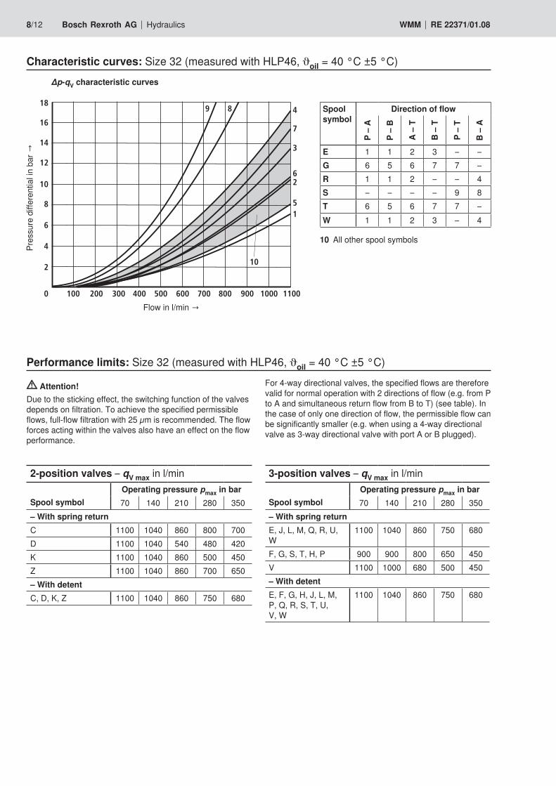
Characteristic curves: Size 32 (measured with HLP46, ϑoil = 40 °C ±5 °C)
Flow in l/min →
Pres
sure
diff
eren
tial in
bar
→
∆p-qV characteristic curves
Performance limits: Size 32 (measured with HLP46, ϑoil = 40 °C ±5 °C)
Attention!Due to the sticking effect, the switching function of the valves depends on filtration. To achieve the specified permissible flows, full-flow filtration with 25 µm is recommended. The flow forces acting within the valves also have an effect on the flow performance.
2-position valves – qV max in l/min
Spool symbolOperating pressure pmax in bar70 140 210 280 350
– With spring returnC 1100 1040 860 800 700D 1100 1040 540 480 420K 1100 1040 860 500 450Z 1100 1040 860 700 650– With detentC, D, K, Z 1100 1040 860 750 680
For 4-way directional valves, the specified flows are therefore valid for normal operation with 2 directions of flow (e.g. from P to A and simultaneous return flow from B to T) (see table). In the case of only one direction of flow, the permissible flow can be significantly smaller (e.g. when using a 4-way directional valve as 3-way directional valve with port A or B plugged).
3-position valves – qV max in l/min
Spool symbolOperating pressure pmax in bar70 140 210 280 350
– With spring returnE, J, L, M, Q, R, U, W
1100 1040 860 750 680
F, G, S, T, H, P 900 900 800 650 450V 1100 1000 680 500 450– With detentE, F, G, H, J, L, M, P, Q, R, S, T, U, V, W
1100 1040 860 750 680
Spool symbol
Direction of flow
P –
A
P –
B
A –
T
B –
T
P –
T
B –
A
E 1 1 2 3 – –G 6 5 6 7 7 –R 1 1 2 – – 4S – – – – 9 8T 6 5 6 7 7 –W 1 1 2 3 – 4
10 All other spool symbols
a b0
a b
43
Ø12
240
26 26
56
290
57
95
3
100
3391
4 x Ø112x Ø6,6
27
T P X
LA B Y
29
158
13
94
1
3
2
4
5
7
9 10
155 / 163
6 8.1
A B Y
A B Y
T P X
L
8.2
F1 F2
F3F4
F5
F6G2
G1
0,01/100
Rzmax 4
Hydraulics Bosch Rexroth AGRE 22371/01.08 WMM 9/12
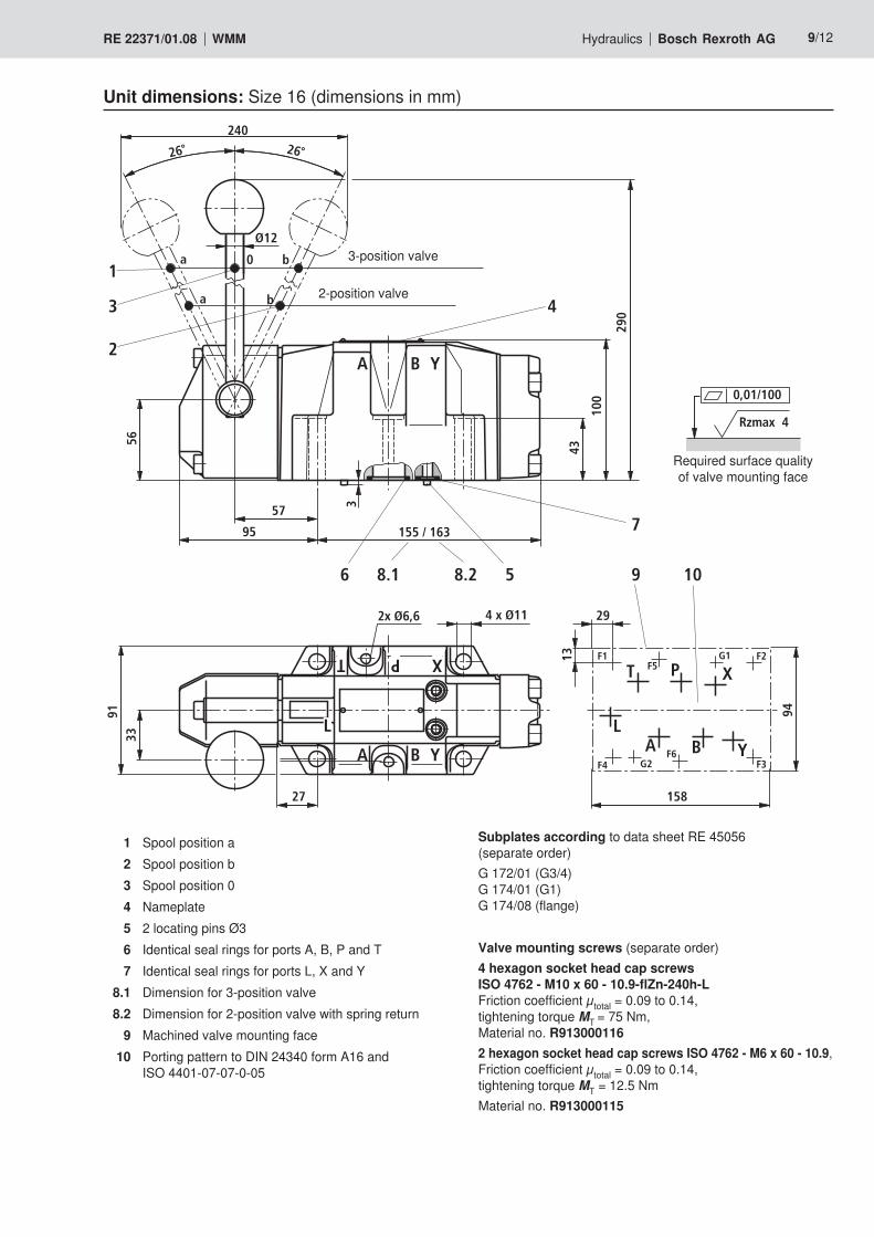
Unit dimensions: Size 16 (dimensions in mm)
1 Spool position a2 Spool position b3 Spool position 04 Nameplate5 2 locating pins Ø36 Identical seal rings for ports A, B, P and T7 Identical seal rings for ports L, X and Y
8.1 Dimension for 3-position valve8.2 Dimension for 2-position valve with spring return
9 Machined valve mounting face10 Porting pattern to DIN 24340 form A16 and
ISO 4401-07-07-0-05
Subplates according to data sheet RE 45056 (separate order)G 172/01 (G3/4) G 174/01 (G1) G 174/08 (flange)
Valve mounting screws (separate order)4 hexagon socket head cap screws ISO 4762 - M10 x 60 - 10.9-flZn-240h-L Friction coefficient µtotal = 0.09 to 0.14, tightening torque MT = 75 Nm, Material no. R9130001162 hexagon socket head cap screws ISO 4762 - M6 x 60 - 10.9, Friction coefficient µtotal = 0.09 to 0.14, tightening torque MT = 12.5 NmMaterial no. R913000115
2-position valve
3-position valve
Required surface quality of valve mounting face
T P Y
BAX
230
24,5 24,5
61
Ø12
4111
330
1
59
a b0
a b1
3
2
93
6 x Ø14
14
58,5
117
34
122
12
21
180
4
4
5 6, 7 9 10
193
A BX
T P YF1 F2
F3F4
F5
F6
G1
G2
0,01/100
Rzmax 4
10/12 Bosch Rexroth AG Hydraulics WMM RE 22371/01.08
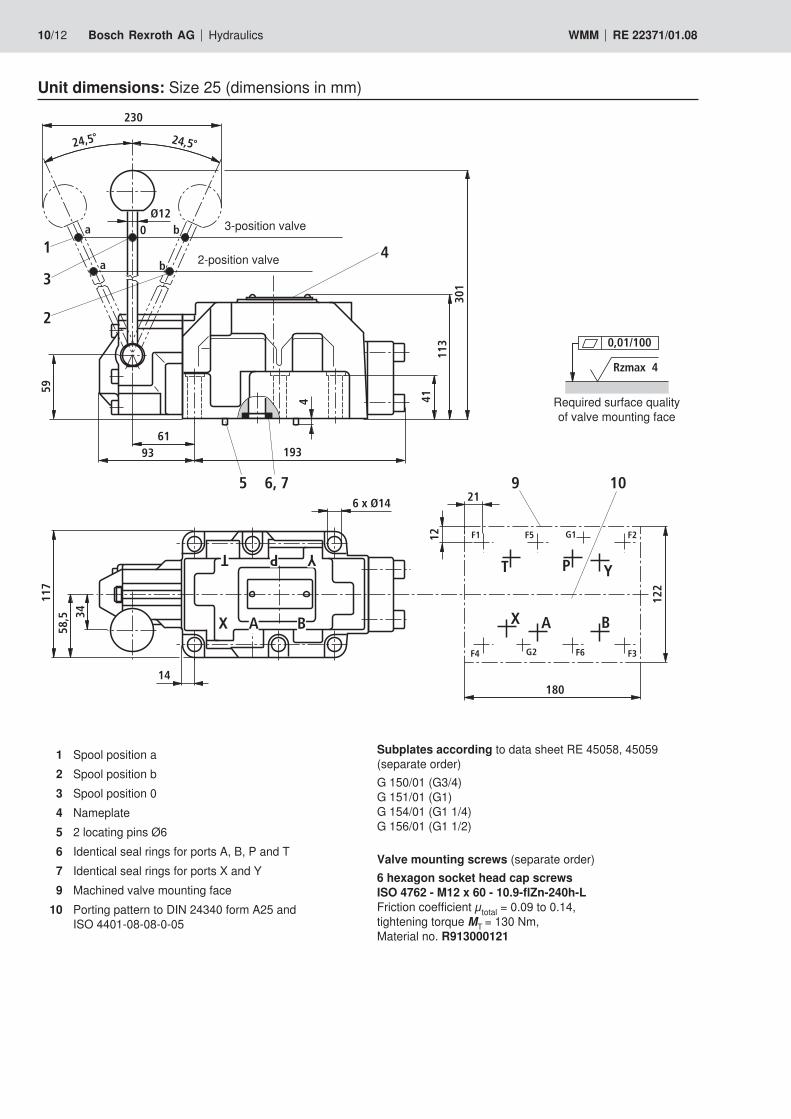
Unit dimensions: Size 25 (dimensions in mm)
1 Spool position a2 Spool position b3 Spool position 04 Nameplate5 2 locating pins Ø66 Identical seal rings for ports A, B, P and T7 Identical seal rings for ports X and Y9 Machined valve mounting face
10 Porting pattern to DIN 24340 form A25 and ISO 4401-08-08-0-05
Subplates according to data sheet RE 45058, 45059 (separate order)G 150/01 (G3/4) G 151/01 (G1) G 154/01 (G1 1/4) G 156/01 (G1 1/2)
Valve mounting screws (separate order)6 hexagon socket head cap screws ISO 4762 - M12 x 60 - 10.9-flZn-240h-L Friction coefficient µtotal = 0.09 to 0.14, tightening torque MT = 130 Nm, Material no. R913000121
2-position valve
3-position valve
Required surface quality of valve mounting face
T P Y
AX
410
30 30
92
Ø18
4919
548
5
99,5
a b0
a b1
3
2
158
1919
276
4
4
5 6, 7
9 10305
B
353
11
X BA
T P Y
X BA
L
6 x Ø33
6 x Ø22
24
68
197
98,5
197
8.1 8.2
F1 F2
F3F4
F5
F6G2
G1
0,01/100
Rzmax 4
Hydraulics Bosch Rexroth AGRE 22371/01.08 WMM 11/12
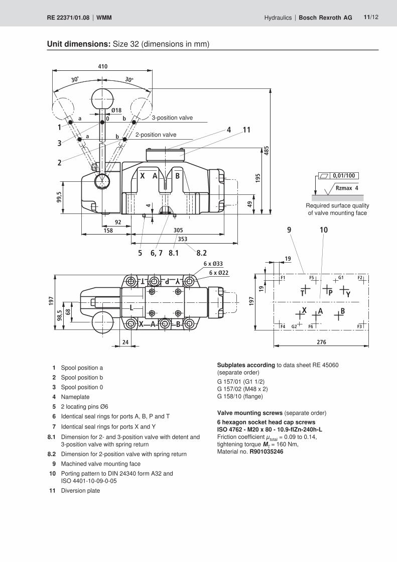
Unit dimensions: Size 32 (dimensions in mm)
1 Spool position a2 Spool position b3 Spool position 04 Nameplate5 2 locating pins Ø66 Identical seal rings for ports A, B, P and T7 Identical seal rings for ports X and Y
8.1 Dimension for 2- and 3-position valve with detent and 3-position valve with spring return
8.2 Dimension for 2-position valve with spring return9 Machined valve mounting face
10 Porting pattern to DIN 24340 form A32 and ISO 4401-10-09-0-05
11 Diversion plate
Subplates according to data sheet RE 45060 (separate order)G 157/01 (G1 1/2) G 157/02 (M48 x 2) G 158/10 (flange)
Valve mounting screws (separate order)6 hexagon socket head cap screws ISO 4762 - M20 x 80 - 10.9-flZn-240h-L Friction coefficient µtotal = 0.09 to 0.14, tightening torque MT = 160 Nm, Material no. R901035246
2-position valve
3-position valve
Required surface quality of valve mounting face

Bosch Rexroth AG HydraulicsZum Eisengießer 197816 Lohr am Main, Germany Phone +49 (0) 93 52 / 18-0 Fax +49 (0) 93 52 / 18-23 [email protected] www.boschrexroth.de
© This document, as well as the data, specifications and other informa-tion set forth in it, are the exclusive property of Bosch Rexroth AG. It may not be reproduced or given to third parties without its consent.The data specified above only serve to describe the product. No state-ments concerning a certain condition or suitability for a certain applica-tion can be derived from our information. The information given does not release the user from the obligation of own judgment and verifica-tion. It must be remembered that our products are subject to a natural process of wear and aging.
12/12 Bosch Rexroth AG Hydraulics WMM RE 22371/01.08
Notes


![2/2, 3/2 and 4/2 directional seat Replaces: 07.06 Valve ...docs-europe.electrocomponents.com/webdocs/0033/0900766b...[104 ± 9 F]) 7 Performance limit (measured with HLP46, ϑ Oil](https://static.fdocument.org/doc/165x107/5abdfc707f8b9aa3088c5289/22-32-and-42-directional-seat-replaces-0706-valve-docs-104-9-f-7-performance.jpg)