
ΑΣΥΡΜΑΤΕΣ-ΔΟΡΥΦΟΡΙΚΕΣ_διάλεξη 10η
36
ΑΣΥΡΜΑΤΕΣ-ΔΟΡΥΦΟΡΙΚΕΣ ΕΠΙΚΟΙΝΩΝΙΕΣ Διδάσκων Λούβρος Σπυρίδων Επίκουρος Καθηγητής - ΤΕΣΥΔ ΔΙΑΛΕΞΗ 10 ΕΠΙΓΕΙΑ ΜΙΚΡΟΚΥΜΑΤΙΚΗ ΖΕΥΞΗ (MW LINK) – ΣΧΕΔΙΑΣΜΟΣ 4 ο Μέρος
-
Upload
ender-sali -
Category
Documents
-
view
217 -
download
0
Transcript of ΑΣΥΡΜΑΤΕΣ-ΔΟΡΥΦΟΡΙΚΕΣ_διάλεξη 10η

ΑΣΥΡΜΑΤΕΣ-ΔΟΡΥΦΟΡΙΚΕΣΕΠΙΚΟΙΝΩΝΙΕΣ
Διδάσκων
Λούβρος Σπυρίδων
Επίκουρος Καθηγητής - ΤΕΣΥΔ
ΔΙΑΛΕΞΗ 10
ΕΠΙΓΕΙΑ ΜΙΚΡΟΚΥΜΑΤΙΚΗ ΖΕΥΞΗ (MW LINK) – ΣΧΕΔΙΑΣΜΟΣ 4ο Μέρος
Σχεδιασμός Μικροκυματικής Ζεύξης κοντινής απόστασης- Short-haul microwave radio design
Μικροκυματική μετάδοση υπό συνθήκες καναλιού ελεύθερες από κατακρυμνήσεις σήματος ισχύος (non-Fading Conditions)
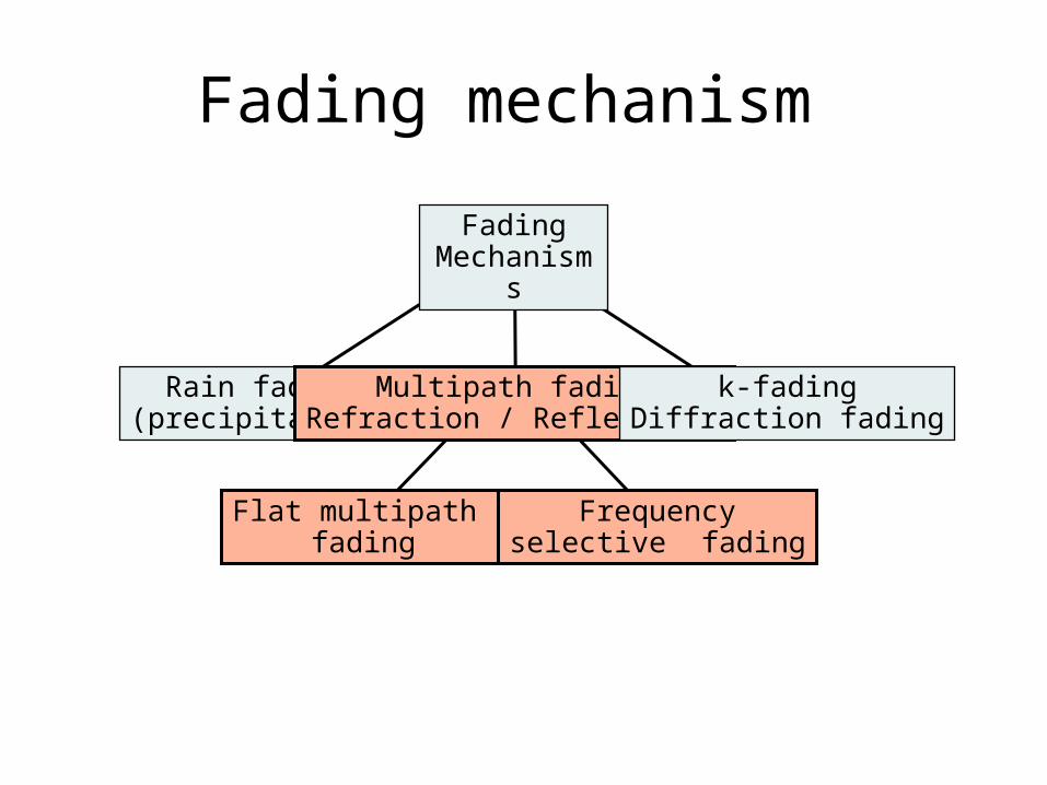
Fading mechanism
Flat multipath fading
Frequencyselective fading
Rain fading(precipitation)
Multipath fadingRefraction / Reflections
k-fadingDiffraction fading
FadingMechanisms
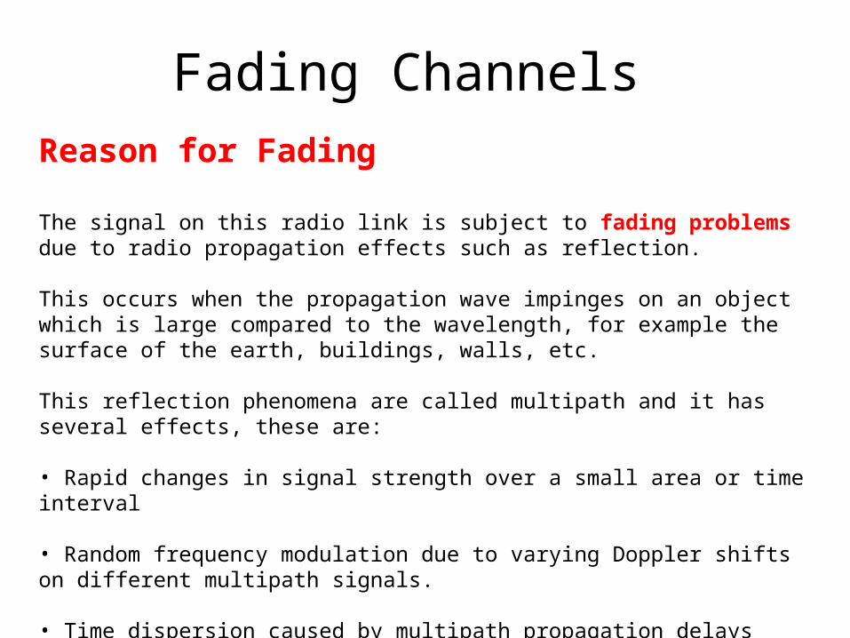
Fading ChannelsReason for Fading
The signal on this radio link is subject to fading problems due to radio propagation effects such as reflection.
This occurs when the propagation wave impinges on an object which is large compared to the wavelength, for example the surface of the earth, buildings, walls, etc.
This reflection phenomena are called multipath and it has several effects, these are:
• Rapid changes in signal strength over a small area or time interval
• Random frequency modulation due to varying Doppler shifts on different multipath signals.
• Time dispersion caused by multipath propagation delays
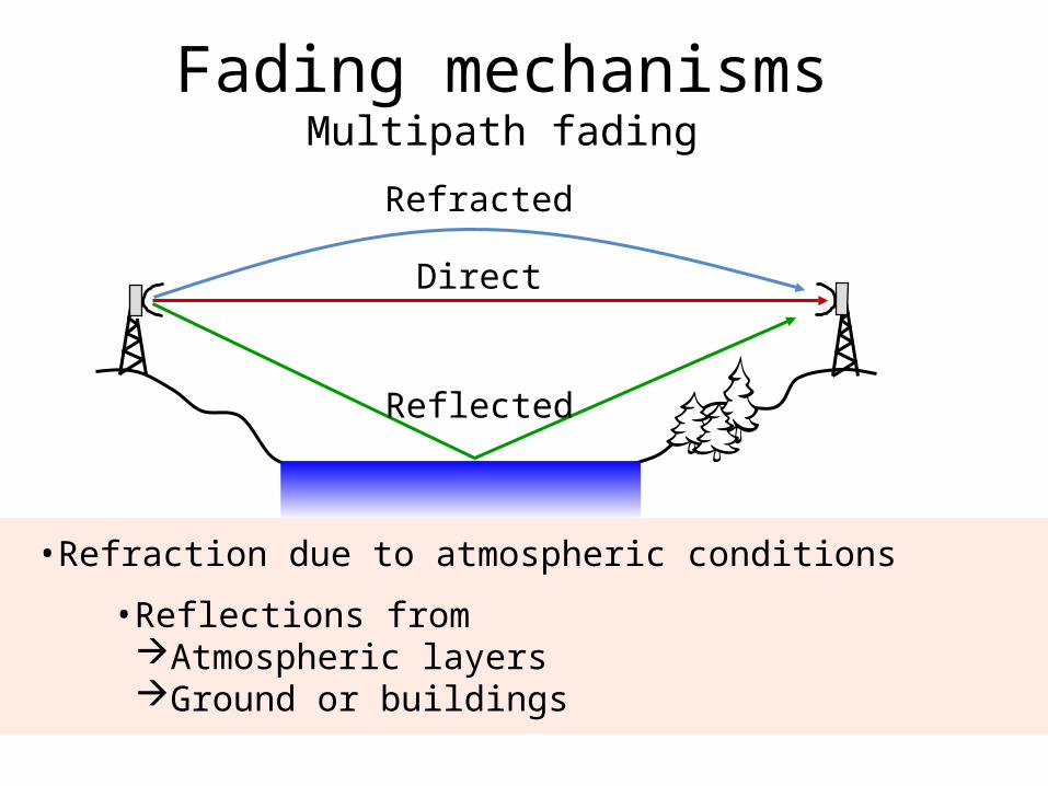
Fading mechanismsMultipath fading
Refracted
Direct
Reflected
•Refraction due to atmospheric conditions
•Reflections from Atmospheric layersGround or buildings
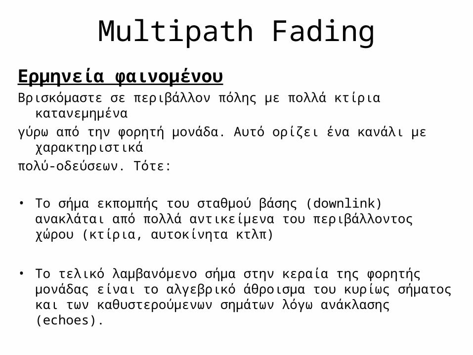
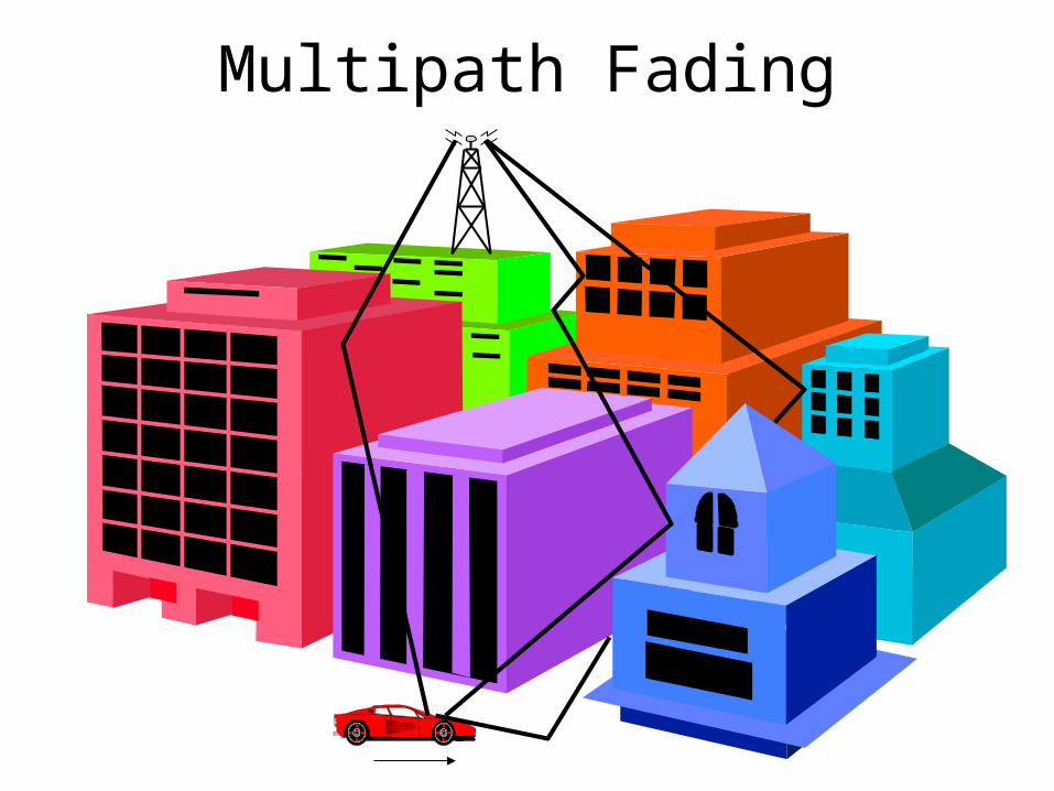
Multipath FadingΕρμηνεία φαινομένουΒρισκόμαστε σε περιβάλλον πόλης με πολλά κτίρια κατανεμημένα γύρω από την φορητή μονάδα. Αυτό ορίζει ένα κανάλι με χαρακτηριστικάπολύ-οδεύσεων. Τότε:
• Το σήμα εκπομπής του σταθμού βάσης (downlink) ανακλάται από πολλά αντικείμενα του περιβάλλοντος χώρου (κτίρια, αυτοκίνητα κτλπ)
• Το τελικό λαμβανόμενο σήμα στην κεραία της φορητής μονάδας είναι το αλγεβρικό άθροισμα του κυρίως σήματος και των καθυστερούμενων σημάτων λόγω ανάκλασης (echoes).
Multipath Fading
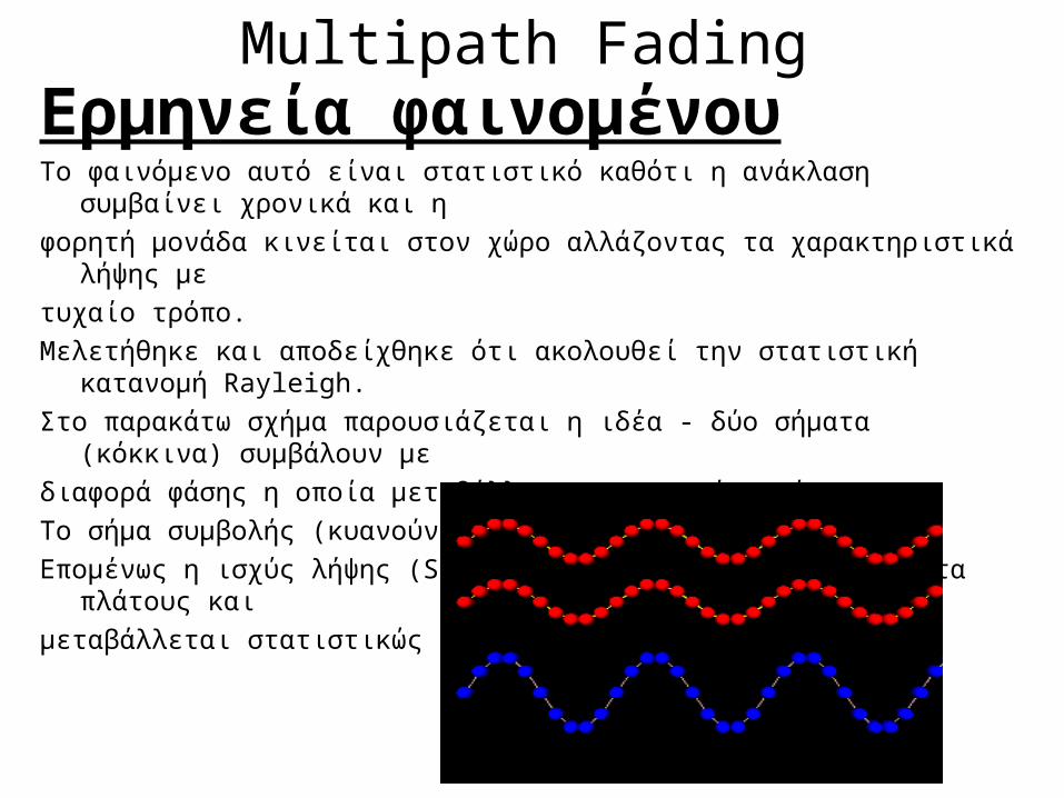
Multipath FadingΕρμηνεία φαινομένουΤο φαινόμενο αυτό είναι στατιστικό καθότι η ανάκλαση συμβαίνει χρονικά και ηφορητή μονάδα κινείται στον χώρο αλλάζοντας τα χαρακτηριστικά λήψης με τυχαίο τρόπο. Μελετήθηκε και αποδείχθηκε ότι ακολουθεί την στατιστική κατανομή Rayleigh.Στο παρακάτω σχήμα παρουσιάζεται η ιδέα - δύο σήματα (κόκκινα) συμβάλουν μεδιαφορά φάσης η οποία μεταβάλλεται με τυχαίο τρόπο. Το σήμα συμβολής (κυανούν) μεταβάλλεται χρονικά. Επομένως η ισχύς λήψης (Signal Strength SS) έχει βυθίσματα πλάτους και μεταβάλλεται στατιστικώς
Multipath Fading
ΠΕΡΙΠΤΩΣΗ 1
• Εάν τα σήματα λήψης (κυρίως και καθυστερούμενα) είναι σχεδόν συμφασικά (Δφ ≈ 0) με σχεδόν ίσα πλάτη τότε το αλγεβρικό άθροισμα τους θα μας δώσει ένα ισχυρότερο σήμα (το άθροισμα των επιμέρους πλατών όλων των συμβαλλόμενων κυμάτων) με μεγάλο βάθος διαμόρφωσης ΑΜ και αργά χρονικά βυθίσματα. Αυτό στην κυματική ονομάζεται ενισχυτική συμβολή
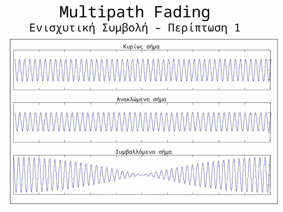
Multipath FadingΕνισχυτική Συμβολή – Περίπτωση 1
Κυρίως σήμα
Ανακλώμενο σήμα
Συμβαλλόμενο σήμα
Multipath Fading
ΠΕΡΙΠΤΩΣΗ 2
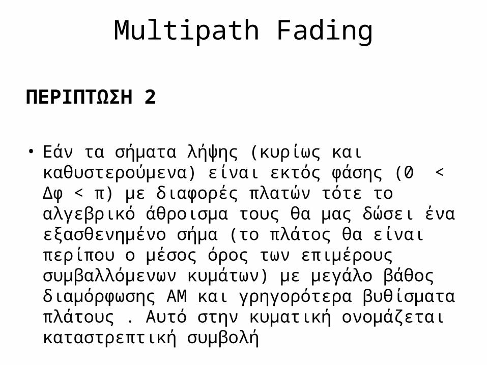
• Εάν τα σήματα λήψης (κυρίως και καθυστερούμενα) είναι εκτός φάσης (0 < Δφ < π) με διαφορές πλατών τότε το αλγεβρικό άθροισμα τους θα μας δώσει ένα εξασθενημένο σήμα (το πλάτος θα είναι περίπου ο μέσος όρος των επιμέρους συμβαλλόμενων κυμάτων) με μεγάλο βάθος διαμόρφωσης ΑΜ και γρηγορότερα βυθίσματα πλάτους . Αυτό στην κυματική ονομάζεται καταστρεπτική συμβολή
Multipath FadingΚαταστρεπτική Συμβολή – Περίπτωση 2
Κυρίως σήμα λήψης (Line of Site – LoS)
Ανακλώμενο σήμα εκτός φάσης με 0 < Δφ < π
Συμβαλλόμενο σήμα
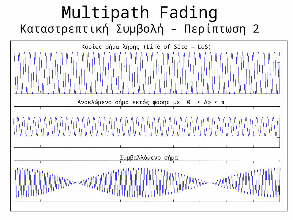
Multipath FadingΠΕΡΙΠΤΩΣΗ 3• Εάν τα σήματα λήψης (κυρίως και καθυστερούμενα) είναι εκτός φάσης
με Δφ = π με διαφορετικά πλάτη τότε το αλγεβρικό άθροισμα τους θα είναι μία διαμόρφωση ΑΜ με βάθος διαμόρφωση το οποίο εξαρτάται από την διαφορά A1 – A2 των πλατών
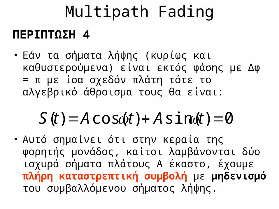
Multipath FadingΠΕΡΙΠΤΩΣΗ 4• Εάν τα σήματα λήψης (κυρίως και καθυστερούμενα)
είναι εκτός φάσης με Δφ = π με ίσα σχεδόν πλάτη τότε το αλγεβρικό άθροισμα τους θα είναι:
• Αυτό σημαίνει ότι στην κεραία της φορητής μονάδος, καίτοι λαμβάνονται δύο ισχυρά σήματα πλάτους Α έκαστο, έχουμε πλήρη καταστρεπτική συμβολή με μηδενισμό του συμβαλλόμενου σήματος λήψης.
0)sin()cos()( tAtAtS
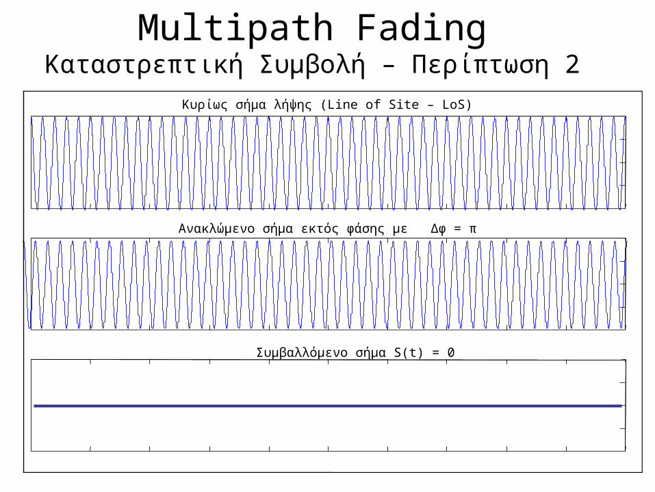
Multipath FadingΚαταστρεπτική Συμβολή – Περίπτωση 2
Κυρίως σήμα λήψης (Line of Site – LoS)
Ανακλώμενο σήμα εκτός φάσης με Δφ = π
Συμβαλλόμενο σήμα S(t) = 0
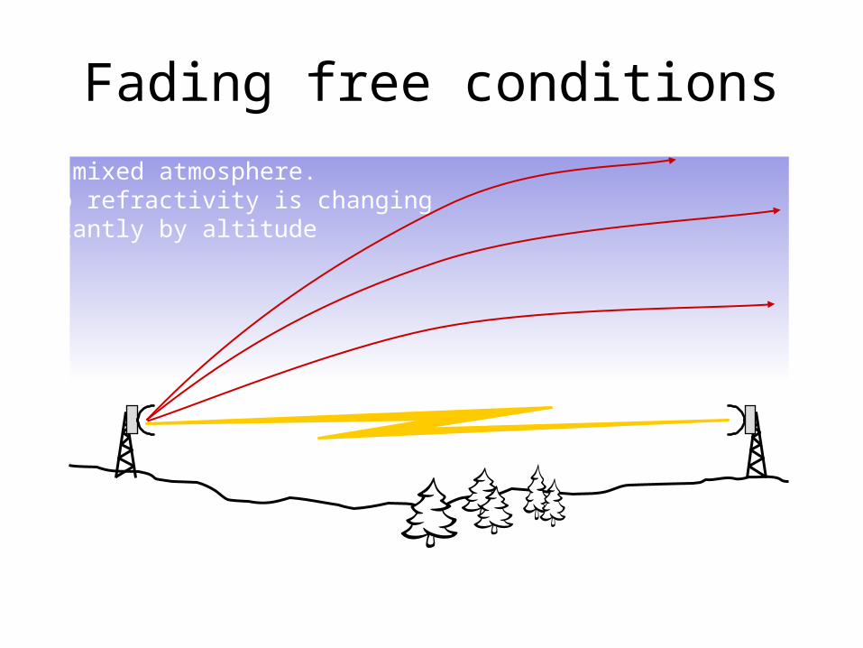
Fading free conditionsWell mixed atmosphere.Radio refractivity is changingconstantly by altitude
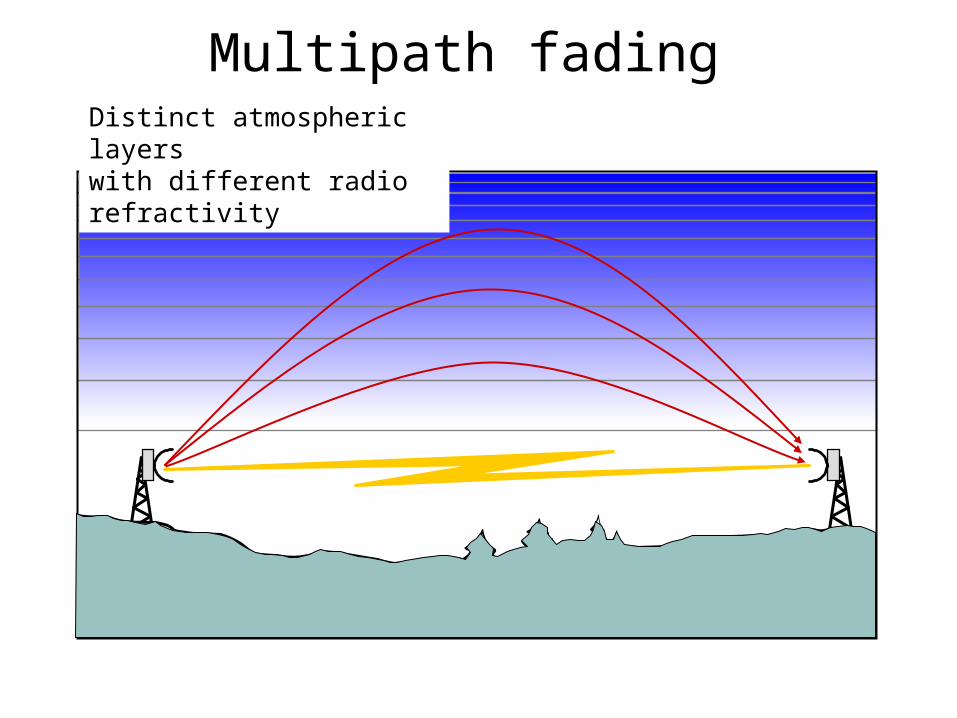
Multipath fading Distinct atmospheric layers with different radio refractivity
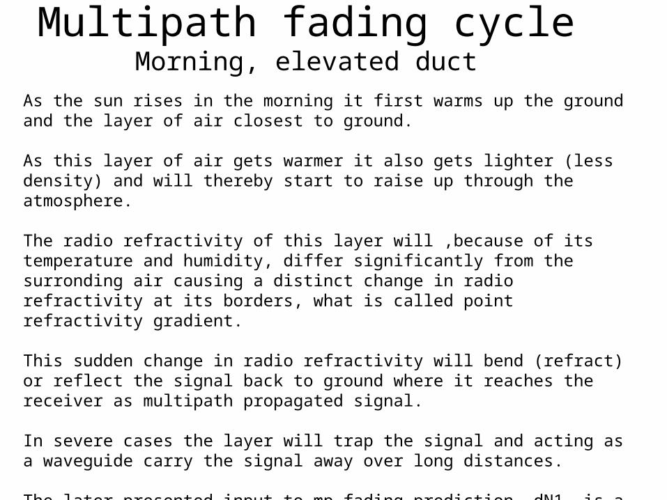
Multipath fading cycleMorning, elevated duct
As the sun rises in the morning it first warms up the ground and the layer of air closest to ground.
As this layer of air gets warmer it also gets lighter (less density) and will thereby start to raise up through the atmosphere.
The radio refractivity of this layer will ,because of its temperature and humidity, differ significantly from the surronding air causing a distinct change in radio refractivity at its borders, what is called point refractivity gradient.
This sudden change in radio refractivity will bend (refract) or reflect the signal back to ground where it reaches the receiver as multipath propagated signal.
In severe cases the layer will trap the signal and acting as a waveguide carry the signal away over long distances.
The later presented input to mp fading prediction, dN1, is a value discribing how high this sudden change in radio refractivity is likely to be.
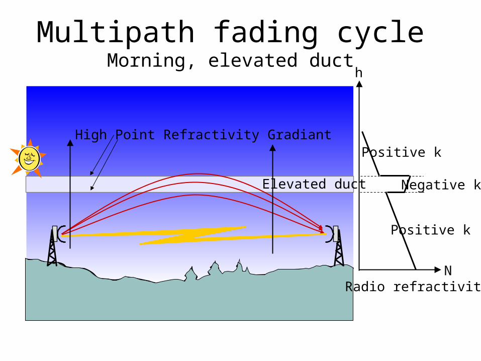
Multipath fading cycleMorning, elevated duct
Elevated duct
High Point Refractivity Gradiant
N
h
Positive k
Negative k
Positive k
Radio refractivity
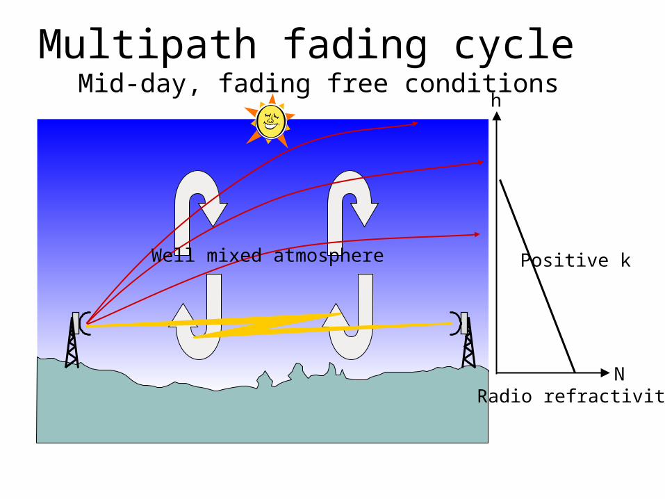
Multipath fading cycle Mid-day, fading free conditions
Well mixed atmosphere
N
h
Positive k
Radio refractivity
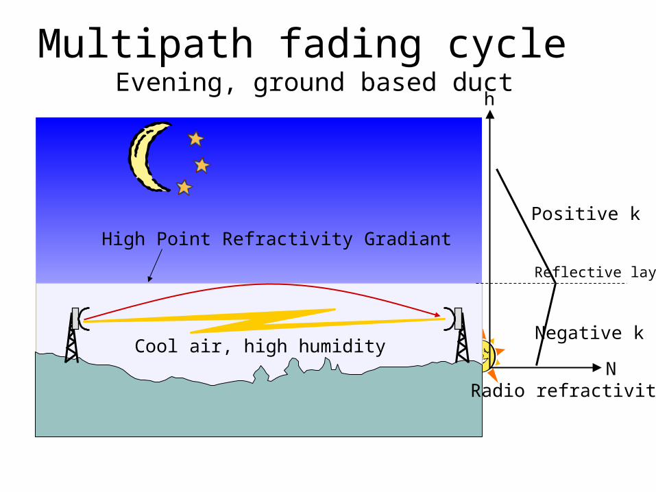
Multipath fading cycle Evening, ground based duct
Cool air, high humidity
High Point Refractivity Gradiant
N
h
Negative k
Positive k
Reflective layer
Radio refractivity
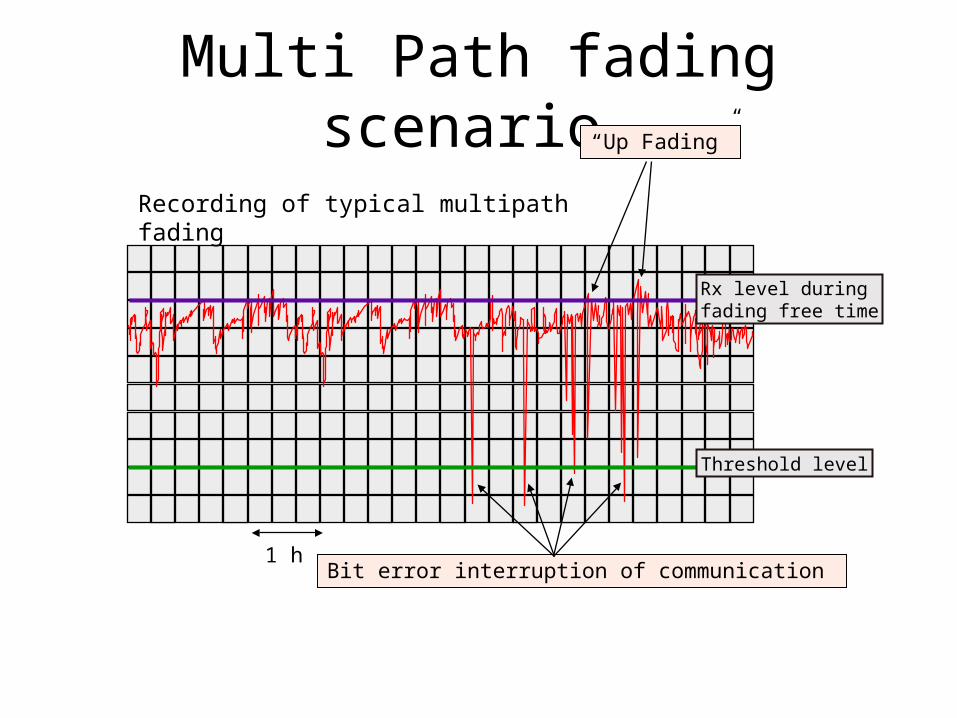
Multi Path fading scenario
1 h
Recording of typical multipath fading
Rx level during fading free time
Threshold level
Bit error interruption of communication
“Up Fading”
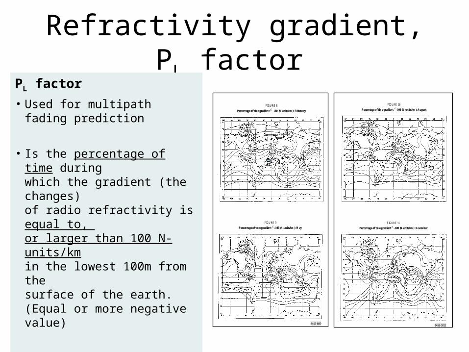
Refractivity gradient, PL factor
0453-089
FIGURE 9
Percentage of time gradient –100 (N-units/km): May
FIGURE 8
Percentage of time gradient –100 (N-units/km): February
0453-1011
FIGURE 11
Percentage of time gradient –100 (N-units/km): November
FIGURE 10
Percentage of time gradient –100 (N-units/km): August
PL factor• Used for multipath fading
prediction • Is the percentage of time during
which the gradient (the changes) of radio refractivity is equal to, or larger than 100 N-units/kmin the lowest 100m from the surface of the earth. (Equal or more negative value)
• Obtained from maps in ITU-R Rec. P.453. The worst case (highest percentage) is to be chosen.
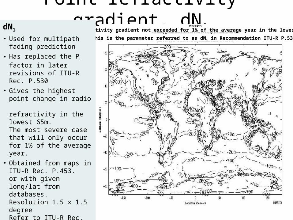
Point refractivity gradient, dN1Refractivity gradient not exceeded for 1% of the average year in the lowest 65m
(This is the parameter referred to as dN1 in Recommendation ITU-R P.530)
dN1
• Used for multipath fading prediction
• Has replaced the PL factor in later revisions of ITU-R Rec. P.530
• Gives the highest point change in radio refractivity in the lowest 65m. The most severe case that will only occurfor 1% of the average year.
• Obtained from maps in ITU-R Rec. P.453. or with given long/lat from databases.Resolution 1.5 x 1.5 degreeRefer to ITU-R Rec. P.453
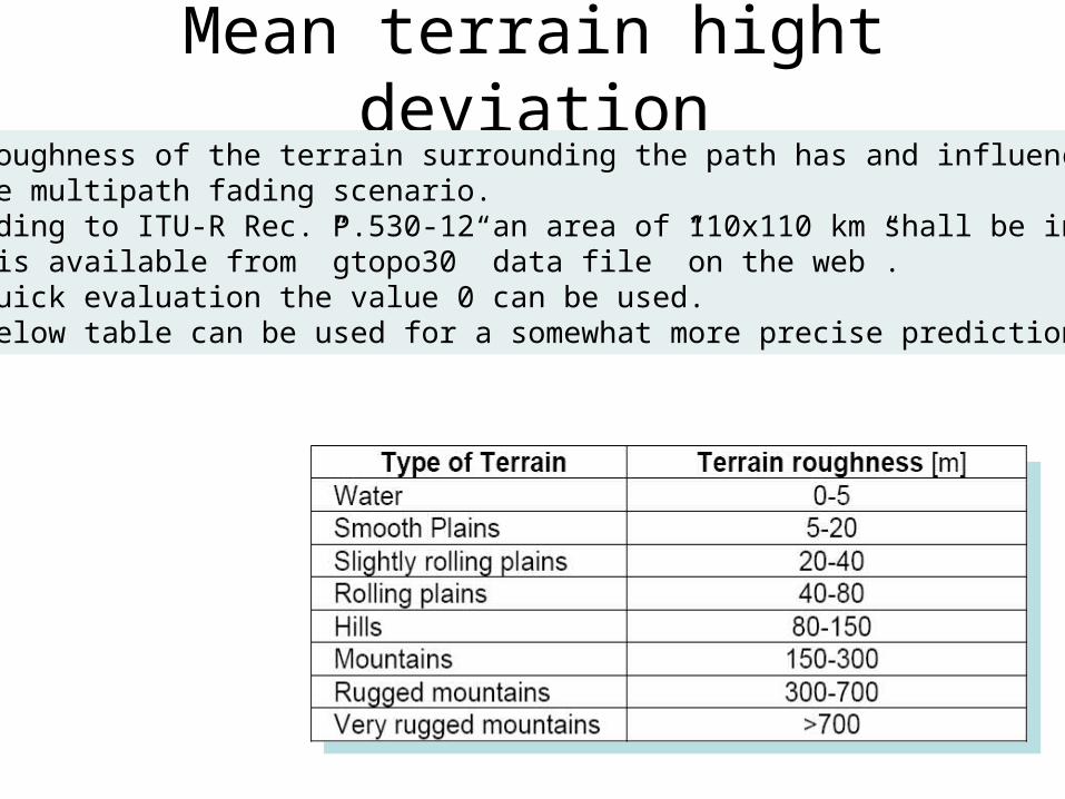
Mean terrain hight deviation• The roughness of the terrain surrounding the path has and influence
on the multipath fading scenario. • According to ITU-R Rec. P.530-12 an area of 110x110 km shall be included• Data is available from ”gtopo30” data file ”on the web”.• For quick evaluation the value 0 can be used.
The below table can be used for a somewhat more precise prediction.
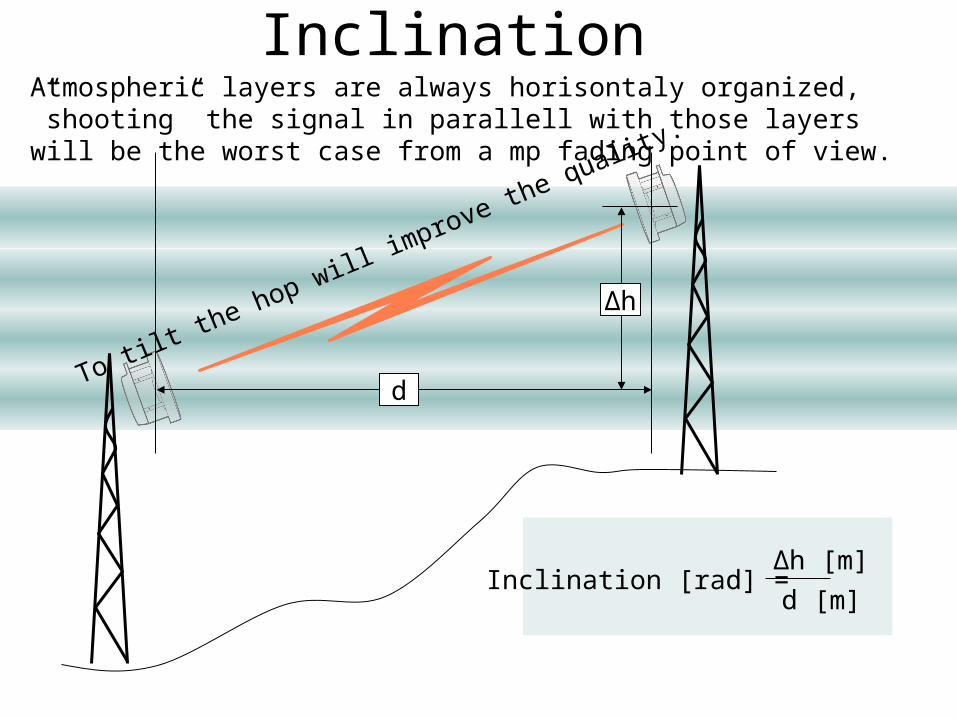
Inclination
Δh
d
To tilt the hop will im
prove the quality.
Inclination [rad] = Δh [m]d [m]
Atmospheric layers are always horisontaly organized, ”shooting” the signal in parallell with those layers will be the worst case from a mp fading point of view.
Flat and Freq. selective mp fadingMultipath fading occurs when the receiver is reached by the same signal via different paths with different propagation time.
The delay between the direct signal and the ”multipath” signal will if it is small give raise to flat multipath fading.
If the delay is long it will give raise to frequency selective multipath fading.
This is the limiting factor for ”long” hops at ”low” frequency (next slide).
Frequency selective multipath fading always holds a flat mp fading component .Flat mp fading occurs if the reflection point is close to the path, for example ground reflections.
Flat and Freq. selective mp fadingFreq. sel. mp fading occurs when the reflection point is far from the path, atmospheric refraction/reflection.
To increase the gain will not contribute to the path performance (beyond a certain point) if freq.sel. mp fading is the limiting factor for the hop length.
This holds because the origin of the freq. sel. mp fading is a matter of time delay, not a matter of gain.
Both flat and freq.sel mp fading will influence the Quality of the hop by causing ESR and SESR.
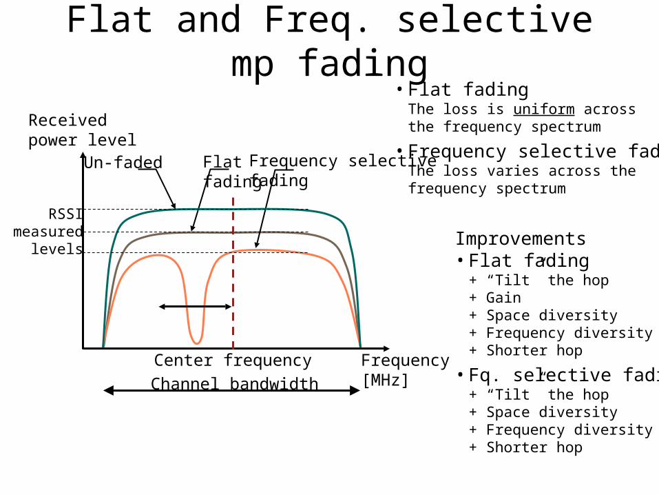
Flat and Freq. selective mp fading
Flat fading
Frequency selective fading
Frequency [MHz]
Received power level
Un-faded
Center frequencyChannel bandwidth
• Flat fadingThe loss is uniform across the frequency spectrum
• Frequency selective fadingThe loss varies across the frequency spectrum
Improvements• Flat fading
+ “Tilt” the hop+ Gain+ Space diversity+ Frequency diversity+ Shorter hop
• Fq. selective fading+ “Tilt” the hop+ Space diversity+ Frequency diversity+ Shorter hop
RSSImeasured
levels
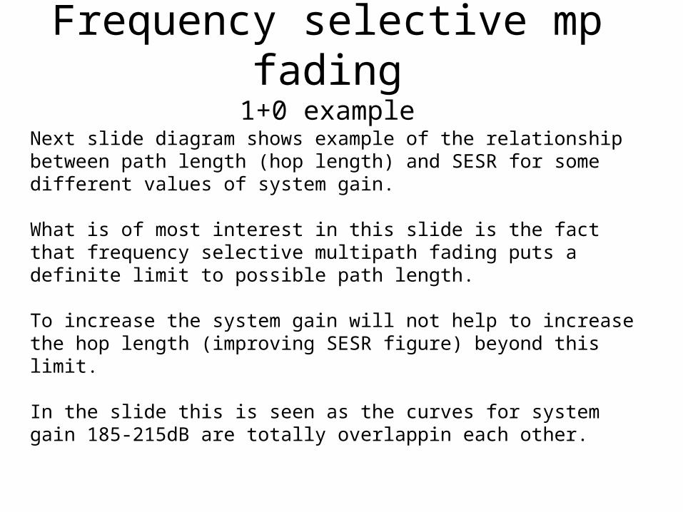
Frequency selective mp fading1+0 example
Next slide diagram shows example of the relationship between path length (hop length) and SESR for some different values of system gain.
What is of most interest in this slide is the fact that frequency selective multipath fading puts a definite limit to possible path length.
To increase the system gain will not help to increase the hop length (improving SESR figure) beyond this limit.
In the slide this is seen as the curves for system gain 185-215dB are totally overlappin each other.
Frequency selective mp fading1+0 example
To beyond this point improve the SESR figures (extend path length) requires the employment of diversity technique.
The slide shows only SESR BBER and ESR will show similar graphs and behaviour. In real path design at ”low” frequencies it is most commonly the SESR objective that is dimensioning. BBER can under certain circomstances be the dimensioning objective but ESR is in practice never the dimensioning objective.
dB values in the slide are ”System gain” defined as As = Pt + GTx + GRx – PthrWhere:Pt = Transmitter output powerGTx = Transmitter antenna gainGRx = Receiver antenna gainPthr = Receiver threshold value
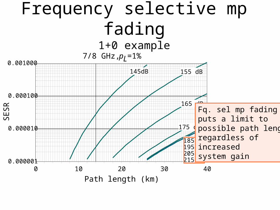
Frequency selective mp fading1+0 example
0.000001
0.000010
0.000100
0.001000
0 10 20 30 40Path length (km)
SE
SR
7/8 GHz, pL=1%
145dB 155 dB
165 dB
175 dB
185 dB195 dB205 dB215 dB
Fq. sel mp fadingputs a limit to possible path lengthregardless of increasedsystem gain
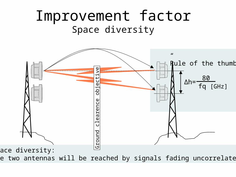
Improvement factorSpace diversity
Δh= 80fq [GHz]
”Rule of the thumb”
• Space diversity: the two antennas will be reached by signals fading uncorrelated
Gro
und
clea
renc
e ob
ject
ive
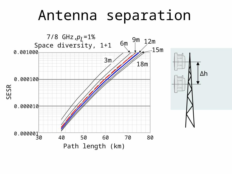
Antenna separation
30 40 50 60 70 80
Path length (km)
0.000001
0.000010
0.000100
0.001000
SE
SR
3m
6m 9m 12m15m
18m
7/8 GHz, pL=1%Space diversity, 1+1
Δh
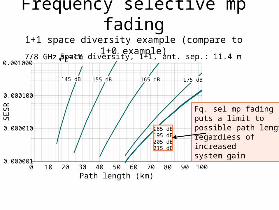
Frequency selective mp fading1+1 space diversity example (compare to 1+0 example)
0 10 20 30 40 50 60 70 80 90 100Path length (km)
7/8 GHz, pL=1%
145 dB 155 dB 165 dB 175 dB
185 dB195 dB205 dB215 dB
Space diversity, 1+1, ant. sep.: 11.4 m
0.000001
0.000010
0.000100
0.001000
SE
SR Fq. sel mp fading
puts a limit to possible path lengthregardless of increasedsystem gain
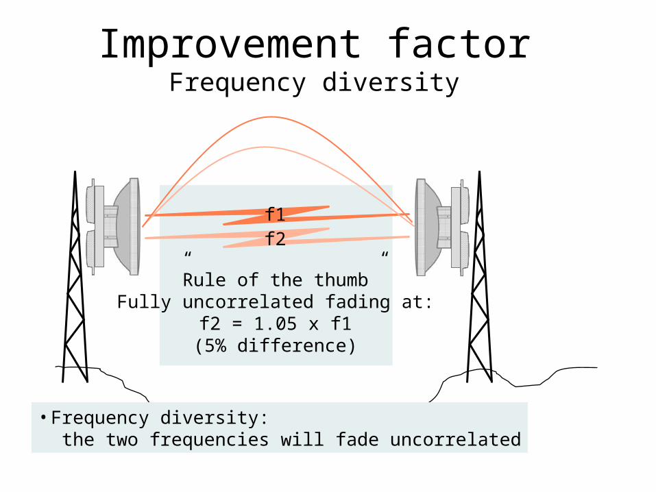
Improvement factorFrequency diversity
• Frequency diversity: the two frequencies will fade uncorrelated
”Rule of the thumb”Fully uncorrelated fading at:
f2 = 1.05 x f1(5% difference)
f1f2


![37ο ΕΤΗΣΙΟ ΣΥΝΕΔΡΙΟ · 2015-05-24 · Συνεδρία 10η Αίθουσα Β’ Παρουσίαση και συζήτηση posters P8 [57-64] 12.30 – 13.30 Συνεδρία](https://static.fdocument.org/doc/165x107/5f10b1ac7e708231d44a5d2c/37-2015-05-24-10-f.jpg)